Timing Diagram (Part 4 - Timing Diagrams Comparison using Motion Simulation in Microsoft Excel)
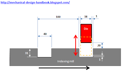
In post [Timing Diagram (Part 1 - No Overlap Movement)], we saw the design requirement that we have to design the die to work together with the indexing mill with the construction as shown below.
 Without detailed calculation, we could end up with a very simple timing diagram as shown below.
 But it's not good enough. The die has to wait for the indexing to finish its movement before moving. This reduces the indexing time of the die, and get high acceleration on the die.
In post [Timing Diagram (Part 2 - Maximum acceleration calculation)], we calculated the maximum acceleration of Cycloidal motion cam profile and saw the opportunity to reduce the acceleration by extending the indexing time.
In post [Timing Diagram (Part 3 - Cycloid Cam Profile Analysis)], we analyzed the cycloid cam profile and see opportunity of overlap motion. Some calculations have been made and we end up with new timing diagram which is smarter than the original one as shown below.
 We calculated the maximum acceleration of the die for this new timing diagram, and we found it was 5 times lower than the acceleration in the first timing diagram.
After all calculations, it's time to see the calculation results. The easiest way is to compare the movement at the same time. The idea is to make simple motion simulation without any timing diagram software or complicated simulation software. I'm using Microsoft Excel again, because it's the main theme of this blog.
We start with plotting the shape of indexing mill and die and add cells called "driver" to change the positions of the indexing mill and the die. Then write VBA code to change the values in "driver" cells to move the parts. Then we can see the movement.
From this example, I don't mean that this is the best timing diagram that give lowest acceleration. We could make it smoother with lower acceleration using "Fifth degree polynomial" together with "Linear" cam profile. But this is enough to show how we can play with timing diagram in the design phase to reduce unnecessary waiting time.
See the result below.
FREE DOWNLOAD EXCEL FILE FROM THIS EXAMPLE
Extract the zip file with password: mechanical-design-handbook.blogspot.com


In post [Timing Diagram (Part 2 - Maximum acceleration calculation)], we calculated the maximum acceleration of Cycloidal motion cam profile and saw the opportunity to reduce the acceleration by extending the indexing time.
In post [Timing Diagram (Part 3 - Cycloid Cam Profile Analysis)], we analyzed the cycloid cam profile and see opportunity of overlap motion. Some calculations have been made and we end up with new timing diagram which is smarter than the original one as shown below.

After all calculations, it's time to see the calculation results. The easiest way is to compare the movement at the same time. The idea is to make simple motion simulation without any timing diagram software or complicated simulation software. I'm using Microsoft Excel again, because it's the main theme of this blog.
We start with plotting the shape of indexing mill and die and add cells called "driver" to change the positions of the indexing mill and the die. Then write VBA code to change the values in "driver" cells to move the parts. Then we can see the movement.
From this example, I don't mean that this is the best timing diagram that give lowest acceleration. We could make it smoother with lower acceleration using "Fifth degree polynomial" together with "Linear" cam profile. But this is enough to show how we can play with timing diagram in the design phase to reduce unnecessary waiting time.
See the result below.
FREE DOWNLOAD EXCEL FILE FROM THIS EXAMPLE
Extract the zip file with password: mechanical-design-handbook.blogspot.com


Comments