Posts

Showing posts from July, 2009

Improve math skills of your kids - Learn step-by-step arithmetic from Math games

Math: Unknown - Step-by-step math calculation game for iOS.


Math: Unknown is much more than a math game. It is a step-by-step math calculation game which will teach users how to calculate in the correct order rather than just asking only the final calculated results.

The app consists of four basic arithmetic operations which are addition, subtraction, multiplication and division. In order to get started, users who are new to arithmetic can learn from animated calculation guides showing step-by-step procedures of solving each type of operation. It is also helpful for experienced users as a quick reference.

Generally, addition and subtraction may be difficult for users who just start learning math especially when questions require carrying or borrowing (also called regrouping). The app helps users to visualize the process of carrying and borrowing in the way it will be done on paper. Once users understand how these operations work, they are ready to learn multiplication and division.

For most students, division is considered as the most difficult arithmetic operation to solve. It is a common area of struggle since it requires prior knowledge of both multiplication and subtraction. To help users understand division, the app uses long division to teach all calculation procedures. Relevant multiplication table will be shown beside the question. Users will have to pick a number from the table which go into the dividend. Multiplication of selected number and divisor is automatically calculated, but the users have to do subtraction and drop down the next digit themselves. Learning whole calculation processes will make them master it in no time.

Math: Unknown is a helpful app for students who seriously want to improve arithmetic calculation skills.

Stepper Motors and Linear Induction Motors

Image
A linear induction motor is made up of an inductor which is made of individual cores with a concentrated poly phase. Linear induction motor can be directly substituted for ball screw drives, hydraulic drives, pneumatic drives, or cam drives . A linear induction motor is basically what is referred to by experts as a “rotating squirrel cage” induction motor . The difference is that the motor is opened out flat. Instead of producing rotary torque from a cylindrical machine it produces linear force from a flat machine. The shape and the way it produces motion is changed, however it is still the same as its cylindrical counterpart. There are no moving parts, however and most experts don’t like that. It does have a silent operation and reduced maintenance as well as a compact size, which appeals many engineers. There is also a universal agreement that it has an ease of control and installation. These are all important considerations when thinking about what type of device you want to crea

Linear Actuators and Linear Motion

Mechanical energy is an area of science that is making strides every day. The study of how actuators produce mechanical motion by converting various forms of energy into mechanical energy is a source of great exploration. Science finds new ways to make use of actuators every day including for medical purposes. Many scientists believe that the more they study these seemingly simple machines, the more they will discover ways of helping mankind. The way in which a linear actuator works is that there is a motor that rotates a drive screw using a synchronous timing belt drive. Some linear actuators can also use a worm gear drive or direct drive. Whichever the choice, the turning of the screw pushes a drive nut along the screw, which in turn pushes the rod out and the rotating the screw in the opposite direction will retract the rod. According to the Association of Sciences, the drive screw is either an ACME or ball thread or is belt-driven which is what gives the machine its motion. A cov

Automotive Braking Methods

Modern automotive brake was invented in the late 19th century, around the same time as the tyre. Up until then, vehicles had wooden wheels that were stopped by large wooden blocks, lowered into position by the driver using a simple lever system. When tyres were invented, the wooden block system was not good enough to stop them at the higher speeds they could achieve, which meant that a new braking system had to be invented. To see the basic principles of modern automotive braking , it is easiest to look at a bicycle. Basically, when you put pressure on the brakes, the pressure is transferred through cables to pull small brake pads onto the side of the tyres, and the force of the friction against the tyres causes them to stop. In fact, cars originally used this very same cable system, but it was found not to work so well at high speeds. Instead, the cables were replaced with hydraulic fluid , which works to transfer the pressure the driver puts on the pedal to the brakes. This works b

Advantage Of Disc Brake Pads

Image
Whether you drive a Chevrolet, a cycle, a van or a pickup truck, you probably have disc brake pads on your vehicle. And even though you probably never think about their function, they are the single most important function on your vehicle. Though there are several types of motor brakes , disc brakes , drum brake , caliper brakes , etc. but the disk brakes are more commonly used. Disc brakes are far better than drum brakes because of their powerful stopping ability. Disc brake pads handle substantially better in wet weather conditions. Why choose anything but the best? What are Disc Brakes ? Put simply, disc brakes consist of two disc brake pads that grasp a rotating disk . The disk, or rotor, connects to the wheels by an axle. You control the grasping power. When you pull on the brake, the clamps come together on the disk, forcing it to stop spinning and causing your vehicle to slow down and eventually stop. How Do You Control Disk Brakes ? In a car, controlling your disk brake

Ball Bearings

Many bearings look very similar, whether they are ball bearings, roller bearings or other bearings. What?! Other bearings? What is a ball bearing, anyway? Ball bearings are formed with an outer ring, an inner ring, a cage or a retainer inside, and a rolling element inside, typically a ball (which is why they are called ball bearings). Roller bearings are formed using a roller instead of a ball, which is why they are called roller bearings (Yes, finally something that makes sense!). Other bearings look just like metal tubes, called plain bearings or bush bearings. They look like sawed off pipe or tube. The principle of bearings is the same principle behind the wheel: things move better by rolling than by sliding. They are called "bearings" because they bear the weight of the object, such as an inline skate or the head of dentist's drill, allowing the object to glide over them with incredible ease and speed. Unlike wheels, they don't turn on an axel; they turn on

How to Build a Robot

Image
Robots as we all know are considered as friendly creature created by human beings as we are created by God. They are created for human being to simplify life even more basically for our daily chores with the specified sequence and even by military for the purpose of doing things which has the danger to life of human beings and thus they are developed over years to substitute human beings in all the fields. Many of us are not that qualified to make a robot by ourselves and that why we all are anxious to know how to make a robot and even depends upon the task we want to create it for. We all have the tendencies of exploring whatever new comes in the field of science and hence a basic prototype robot can be created knowing few basic high end programming stuffs. Robots are almost 30% programming and hence if we target one specific purpose and program it well enough then it serves our purpose and the program mostly used for this is Unix and for beginner's Lego Mindstorms series is th

Sir Isaac Newton and the 3 Laws of Motion

Sir Isaac Newton first presented his three laws of motion in the " Principia Mathematica Philosophiae Naturalis " in 1686. Let's start with the First law of Newton , which states: In the absence of external influences, a material body remains in a condition of rest or continues in uniform and rectilinear movement through inertia . This law is also known as " the law of inertia ". And what is inertia? As a matter of fact, it describes the ability of a body to preserve the initial parameters of its own motion. The formula of the Newton's second law is: F = m • a , where F = the size of the external force, m = size of inert mass, a = size of the acceleration of a body. If we rewrite this as: a = F / m it becomes obvious, that the larger the mass of a body, the greater external effort is required to apply the same acceleration to it. Actually, inertial mass here acts as a measure of its own internal resistance to the influence of the external force. The third

Finite Element Analysis (FEA): Post-processing

Image
The following four-article series was published in a newsletter of the American Society of Mechanical Engineers (ASME) . It serves as an introduction to the recent analysis discipline known as the finite element (FEM). The author is an engineering consultant and expert witness specializing in finite element analysis. FINITE ELEMENT ANALYSIS: Post-processing by Steve Roensch, President, Roensch & Associates Last in a four-part series After a finite element model has been prepared and checked, boundary conditions have been applied, and the model has been solved, it is time to investigate the results of the analysis. This activity is known as the post-processing phase of the finite element method. Post-processing begins with a thorough check for problems that may have occurred during solution. Most solvers provide a log file, which should be searched for warnings or errors, and which will also provide a quantitative measure of how well-behaved the numerical procedures were

Finite Element Analysis (FEA): Solution

Image
The following four-article series was published in a newsletter of the American Society of Mechanical Engineers (ASME) . It serves as an introduction to the recent analysis discipline known as the finite element method (FEM). The author is an engineering consultant and expert witness specializing in finite element analysis. FINITE ELEMENT ANALYSIS: Solution by Steve Roensch, President, Roensch & Associates Third in a four-part series While the pre-processing and post-processing phases of the finite element method are interactive and time-consuming for the analyst, the solution is often a batch process, and is demanding of computer resource. The governing equations are assembled into matrix form and are solved numerically. The assembly process depends not only on the type of analysis (e.g. static or dynamic), but also on the model's element types and properties, material properties and boundary conditions. In the case of a linear static structural analysis, the assembled equa

Finite Element Analysis (FEA): Pre-processing

Image
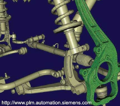
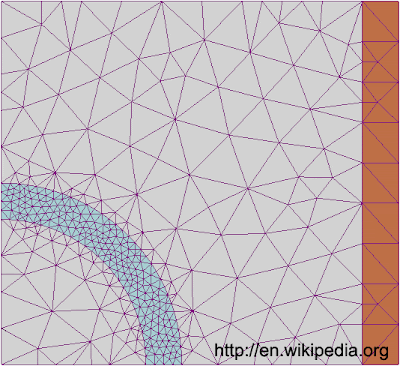
The following four-article series was published in a newsletter of the American Society of Mechanical Engineers (ASME) . It serves as an introduction to the recent analysis discipline known as the finite element method (FEM). The author is an engineering consultant and expert witness specializing in finite element analysis. FINITE ELEMENT ANALYSIS: Pre-processing by Steve Roensch, President, Roensch & Associates Second in a four-part series As discussed in Finite Element Analysis (FEA): Introduction , finite element analysis is comprised of pre-processing, solution and post-processing phases. The goals of pre-processing are to develop an appropriate finite element mesh, assign suitable material properties, and apply boundary conditions in the form of restraints and loads. The finite element mesh subdivides the geometry into elements , upon which are found nodes . The nodes, which are really just point locations in space, are generally located at the element corners and perhaps nea

Finite Element Analysis (FEA): Introduction

Image
The following four-article series was published in a newsletter of the American Society of Mechanical Engineers (ASME) . It serves as an introduction to the recent analysis discipline known as the finite element method (FEM). The author is an engineering consultant and expert witness specializing in finite element analysis. FINITE ELEMENT ANALYSIS: Introduction by Steve Roensch, President, Roensch & Associates First in a four-part series Finite element analysis (FEA) is a fairly recent discipline crossing the boundaries of mathematics, physics, engineering and computer science. The method has wide application and enjoys extensive utilization in the structural, thermal and fluid analysis areas. The finite element method is comprised of three major phases: (1) pre-processing , in which the analyst develops a finite element mesh to divide the subject geometry into subdomains for mathematical analysis, and applies material properties and boundary conditions. (2) solution , during whic