
Featured Post

Why I Wrote The Sheet Mechanic (And Why Calculations Aren’t Enough)

For engineers who already know the math—but still lose projects. For the last few years, I’ve been sharing technical guides here on Mechanical Design Handbook —how to size a motor, how to calculate fits, and (as you recently read) how to choose between timing belts and ball screws. But after 25 years in industrial automation, I realized something uncomfortable: Projects rarely fail because the math was wrong. They fail because: The client changed the scope three times in one week. A critical vendor lied about a shipping date (and no one verified it). The installation technician couldn’t fit a wrench into the gap we designed. University taught us the physics. It didn’t teach us the reality. That gap is why I wrote my new book, The Sheet Mechanic . This is not a textbook. It is a field manual for the messy, political, and chaotic space between the CAD model and the factory floor. It captures the systems I’ve used to survive industrial projec...
NEW RELEASE: Stop trying to be a Hero. Start being a Mechanic. Get "The Sheet Mechanic" on Amazon »
Disclosure: As an Amazon Associate, I earn from qualifying purchases.

Gauss Elimination: Partial Pivoting & Zero Errors (Part 3)

Visualization of Partial Pivoting in Gauss Elimination to prevent division by zero

Figure 1: Partial Pivoting involves swapping rows to avoid zero pivots.

The "Fatal Flaw" in Basic Code

In our previous post, Gauss Elimination (Part 2), we derived the mathematical foundation of the algorithm. However, if you implement that raw math directly into code (VBA, MATLAB, or C++), your program will eventually crash.

Why? Because the basic algorithm assumes the diagonal element (the pivot) is never zero. In the real world of engineering simulations, zeros happen frequently.

Advertisement

The Problem: Division by Zero

Let's look at a standard solvable system of equations:
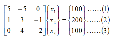
The first step of the algorithm is to normalize the first row by dividing by the coefficient of x1 (which is 5). Since 5 is not zero, this works perfectly.

But what if the equations were rearranged?
Mathematically, the order of equations doesn't matter. But computationally, it changes everything. Look at this arrangement:

Here, the coefficient of x1 is 0. The computer attempts to divide by zero, resulting in a runtime error.

The Hidden Danger: Small Numbers

Even if the number isn't zero, but is very small (e.g., 0.000001), it causes Round-off Errors. Dividing by a tiny number creates a massive result, which can cause the computer to lose precision in the remaining digits. This is known as an "Ill-conditioned system."

The Solution: Partial Pivoting

To solve this, we use a technique called Partial Pivoting. Before performing the elimination step on a column, the algorithm must:

  1. Search: Look down the current column (below the diagonal).
  2. Identify: Find the row with the largest absolute value.
  3. Swap: Switch the current row with that row.

By ensuring the largest possible number is always in the pivot position, we avoid division by zero and minimize round-off errors.

Advertisement

Next Part: The Final Code

Now that we understand the logic and the safety features required, we are ready to build the robust Excel VBA tool.

Continue to Part 4:
Solving System of Equations using Gauss Elimination Method (Part 4: The Final Program)

References

Comments

Popular posts from this blog

Ball Detent Torque Limiter – Working Principle & Selection

Figure 1: The ball detent mechanism provides precise overload protection by disengaging instantly when the torque limit is exceeded. The First Line of Defense: Overload Clutches In high-speed automation and heavy industrial machinery, a "jam" is not a matter of if , but when . Whether it is a cardboard box getting stuck in a packaging machine or a tool crashing in a CNC lathe, the resulting torque spike can destroy gearboxes, twist shafts, and burn out expensive servo motors in milliseconds. A torque limiter (or overload clutch) is the mechanical fuse of the drive system. While electronic monitoring (current limiting) is common, it is often too slow to prevent physical damage from the massive kinetic energy stored in the system inertia. A mechanical torque limiter provides a physical disconnect that operates in a fraction of a second. Search for Torque Limiters & Safety Couplings Advertisement Why Choose ...

Taper-Lock Bushing Failures: The Physics of Wedge Angles

The Failure Scenario: A technician is installing a heavy 20-inch cast-iron V-belt sheave onto a motor shaft using a standard Taper-Lock® bushing. To make future removal easier, they apply a generous coat of anti-seize lubricant to the tapered surface. They tighten the set screws with an impact wrench. Instantly, a loud "CRACK" echoes through the shop. The massive cast-iron hub has split perfectly in half. The Cause: The technician misunderstood the physics of mechanical wedges and friction. By lubricating the taper and using unregulated torque, they generated a radial expansion force that exceeded the Ultimate Tensile Strength of the cast iron, causing a catastrophic hoop stress failure. Tapered bushings (including Taper-Lock and QD styles) are the industrial standard for mounting sprockets, gears, and pulleys to shafts. They rely on the mechanical advantage of a wedge to create massive clamping friction. This guide explains the physics of wedge mechanics, the de...

Polynomial Cams: Analysis & Design Pitfalls (Part 3)

Figure 1: Mathematical coefficients determine the physical shape. Poor math leads to physical defects like the "dip" shown on the right. In [ Polynomial Cam Function (Derivation of Fifth-degree function) - Part 2 ], we derived the equations for the Fifth-Degree (3-4-5) Polynomial . Advertisement Now, we apply this math to the real world of Mechanical Cam Design . The shape of the physical cam is determined by plotting these functions. Unlike a standard Cycloid curve, the polynomial allows us to manipulate the Start Velocity (v 0 ) and End Velocity (v 1 ) of the follower. However, this flexibility requires careful design. If the coefficients are not balanced, the physical cam profile can develop "dips" or negative slopes, causing the mechanical linkage to behave unpredictably. Case 1: Standard Dwell-to-Dwell (Zero Velocity) Figure 2: The standard profile (v 0 =0, v 1 =0). Safe, smooth, and ide...