How to use Unigraphics NX4 Motion Simulation in Timing Diagram Design Process - Part 5
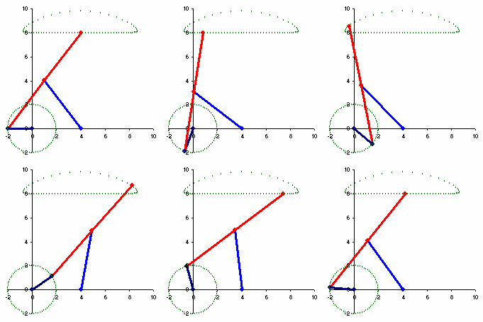
The result of timing diagram design using overlapping motion with fifth-degree (3-4-5) polynomial and linear cam functions can be simulated in 3D motion. The simulation is done using Kinematics environment in Unigraphics (UG) NX4 Motion simulation module. The "spreadsheet run" command is used to control the motions of all driving joints as per the timing diagram. Mechanical Design Engineer can then modify and improve the timing diagram before releasing his design for manufacturing.
Here is the NX4 Motion simulation results.
Related articles:
Here is the NX4 Motion simulation results.
Related articles:
- How to use Unigraphics NX4 Motion Simulation in Ti...
- How to use Unigraphics NX4 Motion Simulation in Ti...
- How to use Unigraphics NX4 Motion Simulation in Ti...
- How to use Unigraphics NX4 Motion Simulation in Ti...
- Practical Unigraphics NX Modeling for Engineers
- NX 6 for Designers
- Engineering Design Communication and Modeling Using Unigraphics® NX
- Advanced Unigraphics NX2 Modeling and Assemblies
- Parametric Modeling with UGS NX6
- Basic and Intermediate NX4 Modeling, Drafting, and Assemblies
- Konstruieren mit Unigraphics NX 4


Comments